


For specific design and application, please strictly follow current local electrical codes for proper selection and installation of protection devices. This guide is prepared based on ABYC E-11 and NEC standards; standards are updated periodically, please refer to the latest versions.
For your safety, we strongly recommend installing appropriate overcurrent protection devices (fuses or circuit breakers) at both the input and output of energy equipment (such as solar panels, batteries, inverters).
Fuse vs. Circuit Breaker: Feature Comparison
| Comparison Dimension | Fuse | Circuit Breaker |
|---|---|---|
| Core Principle | Fusible element melts on overcurrent, single-use. | Thermal-magnetic / electronic trip, reusable. |
| Rated Voltage | Must be ≥ system maximum voltage. | Must also be ≥ system maximum voltage, and must use a DC-rated model with proper arc-extinguishing capability. |
| Interrupting Capacity (AIC) | DC interrupting rating is typically lower than the same model's AC rating (due to no natural zero-crossing in DC). Must strictly follow the manufacturer's DC interrupting rating (e.g., Class T = 20kA @ 125VDC; ANL varies by manufacturer, typically in the 2kA–5kA range). | Typically 5kA–25kA (DC). At high DC voltage and high current, a DC-rated breaker is required; ordinary AC breakers cannot extinguish DC arcs. |
| Arc Extinction | Suitable for clearing very large fault currents; strong arc-extinguishing capability. | Ordinary AC breakers cannot extinguish DC arcs and are prone to contact welding or explosion when used on the DC side; must use DC-rated models with magnetic blow-out or arc-chute design (DC MCB/MCCB). |
| Response Time | Fast-acting types (e.g., gR/aR) respond very quickly. | Thermal trip has a delay (seconds); magnetic trip is faster. |
| Post-Fault Handling | Single-use. Must replace with a new fuse after blowing. | Resettable. Simply press the reset button or toggle the switch to restore power after tripping. |
| Maintenance Cost | Higher long-term cost (need to purchase and stock spare parts). | More convenient – no replacement parts needed. |
| Initial Cost | Lower. | Higher. |
| Isolation & Operation | No clear status indication after blowing; not convenient for manual disconnect. | Can serve as an isolator with clear ON/OFF status indication, convenient for manual circuit disconnection during maintenance. |
| Applicable Scenarios | PV string protection, battery main circuit protection. Protecting sensitive equipment, DC side with high short-circuit risk, projects requiring high reliability or budget-limited. | Battery side disconnect switch with protection (common for low-voltage DC < 150V). Branch circuits requiring frequent switching, convenient O&M, as main system switch, or budget-sufficient projects. |
| Sizing Formula |
PV side: Fuse rating = Isc of that branch × 1.56, round up. Battery side: Fuse rating = Max continuous charge current × 1.25, round up. |
PV side: Breaker rating = Isc × 1.56, round up. Battery side: Breaker rating = Max continuous charge current × 1.25, round up. |
⚠️Critical Warnings:
- Ordinary AC circuit breakers are strictly prohibited on the DC side!
- Always verify the DC voltage rating of fuses/breakers. Automotive blade fuses, MIDI/MEGA, and most ANL fuses are rated only at 32VDC and cannot reliably extinguish arcs in 48V systems (charge voltage up to 58.4V). For 48V systems, select Class T or DC MCB rated ≥ 58VDC (125VDC or higher recommended).
- Never use protection devices with insufficient interrupting capacity (AIC). In a lithium battery main circuit, if the fuse AIC is lower than the available short-circuit current, the fuse housing may burst or the arc may persist during a short circuit — this is more dangerous than having no protection at all.
- Arc flash hazard: High-current DC systems (especially lithium battery banks) produce dangerous DC arcs when breaking a loaded circuit; the arc temperature is extremely high and will not self-extinguish. Before operation: ① disconnect all power sources; ② verify zero voltage with a multimeter; ③ wear insulated gloves and safety goggles. Never plug/unplug connectors or remove fuses under load.
Before choosing a fuse or breaker size, confirm the conductor can safely carry the expected current; Renogy’s DC wire gauge selection guide explains how cable length, current, and voltage drop affect that choice.
Final Selection Recommendation
- Budget priority, maximum safety: Choose fuses – they offer the highest interrupting ratings.
- Convenience, easy daily maintenance: Choose circuit breakers – their resettable feature brings great convenience.
Whether using fuses or circuit breakers, ensure connections are secure to prevent loosening and heating from vibration. Also, the core principle of "protecting the conductor" must always be followed: the fuse/breaker rating must not exceed the safe ampacity of the conductor it protects. This guide uses fuses as the primary example for detailed explanation.
Core Safety Principles
Principle 1: The Fuse Protects the Wire, Not the Equipment
The core purpose of a fuse is to melt before the conductor reaches its maximum allowable temperature, thereby protecting the entire circuit from thermal damage and fire risk. Internal equipment faults should be handled by the equipment's own fuse or protection circuit.
Principle 2: Dual-Constraint Sizing
- Upper constraint: Fuse rated current ≤ conductor ampacity.
- Lower constraint: Fuse rated current ≥ maximum continuous load current × 1.25 (continuous load requirement, per NEC 210.20(A) / 215.3).
Principle 3: Interrupting Capacity Constraint (AIC)
For battery circuits, especially lithium systems, the fuse's DC interrupting capacity (AIC) must be ≥ the available short-circuit current of the circuit. A single 100Ah LiFePO₄ battery can deliver 2000–5000A short-circuit current; multiple in parallel can exceed 10kA. For the battery main circuit, prefer Class T fuses (20kA @ 125VDC) or other high-AIC fuses.
| NOTE The above constraints may conflict. When the "×1.25 value" exceeds the ampacity of the selected wire gauge, you must increase the wire gauge, not reduce the fuse rating. Never reduce the fuse rating to accommodate a smaller wire gauge — this is one of the most common causes of fire in DC systems. |
Additional note: The battery management system (BMS) built into lithium batteries typically has fast short-circuit protection (response time ~200–600µs) and can serve as a backup protection layer. However, the BMS should not replace the external main-circuit fuse — they complement each other. The external fuse handles sustained severe overcurrent and unforeseen extreme short circuits, while the BMS provides an additional electronic layer of protection.
Fuse Calculation Formulas & Selection Tables
1. Solar Panel (PV String) Fuses
Key Concept Clarification:
- Branch fuse: Installed at the positive output of each PV string to protect that branch cable. Use the Isc value of that specific branch for calculation.
- Main fuse: Installed at the output of the combiner box or busbar to protect the main trunk. Use the total Isc of all parallel branches for calculation.
Formula: Fuse rating = Isc of that branch (or total) × 1.56 (= 1.25 continuous load × 1.25 irradiance enhancement), round up.
This calculation method originates from NEC Article 690 (Photovoltaic Systems), specifically NEC 690.9 (Overcurrent Protection) and 690.8 (Circuit Ampacity Calculation).
You may also refer to the table below:
| Isc (or total Isc) range | Calculated value (Isc × 1.56) | Standard fuse rating after rounding up |
|---|---|---|
| 0 – 6.41A | 0 - 10A | 10A |
| 6.41 – 9.62A | 10 – 15A | 15A |
| 9.62 – 12.82A | 15 – 20A | 20A |
| 12.82 – 16.03A | 20 – 25A | 25A |
| 16.03 – 19.23A | 25 – 30A | 30A |
| 19.23 – 25.64A | 30 – 40A | 40A |
Hard upper limit: The selected fuse rating must not exceed the "Maximum Series Fuse Rating" stated in the solar panel datasheet. When the 1.56 formula result conflicts with this limit, the panel datasheet limit takes precedence. If the rounded-up value exceeds the panel's maximum series fuse rating, you must choose a panel with lower Isc or reduce the number of parallel strings.
Quantity required:
- Single panel or single string (no parallel): One fuse can be installed at the positive output of the string (not mandatory but recommended). When panels are in series, current flows along a single continuous path and remains essentially constant. Thus, a single appropriately rated fuse at the positive output protects the entire string.

- Parallel ≤ 2 strings: Branch fuses are not required (not mandatory, but strongly recommended) provided that the sum of Isc of the remaining branches does not exceed the panel's "Maximum Series Fuse Rating".
- Parallel ≥ 3 strings: Each string's positive output must have an independent fuse (mandatory). Parallel configurations require individual branch protection. If one panel (or sub-array) short-circuits or fails, healthy branches will feed current into the faulty branch, causing damage or danger. To prevent such reverse or abnormal current, install a fuse at the positive output of each parallel panel (or each parallel sub-array).
- More precise criterion: When the "sum of Isc of the remaining branches" exceeds the panel's "Maximum Series Fuse Rating", individual string fuses are mandatory.

2. Charge Controller / DC-DC Charger to House Battery Fuse
Formula: Fuse rating = Equipment maximum charge current × 1.25, round up.
Fuse installation location: Install the fuse within 7 inches (175 mm) of the battery positive terminal to minimize the length of unprotected wiring.
Charge controller placement: For accurate voltage sensing, the charge controller should be installed as close to the battery as possible — ideally within 20cm, maximum 1m (3.3ft), and use adequate wire gauge to reduce voltage drop.
| Equipment maximum charge current | Fuse rating |
|---|---|
| 10A | 15A – 20A fuse |
| 15A | 20A – 25A fuse |
| 20A | 25A – 30A fuse |
| 25A | 35A – 40A fuse |
| 30A | 40A – 50A fuse |
| 40A | 50A – 60A fuse |
| 50A | 65A – 80A fuse |
| 60A | 80A – 90A fuse |
| 100A | 125A – 150A fuse |
3. DC-DC Charger to Starter Battery Fuse
Key Concept Clarification: Use the charger's maximum input current, not the output current. This parameter can be found in the DC-DC product datasheet.
Formula: Fuse rating = Charger maximum input current × 1.25, round up.
Fuse installation location: The fuse must be installed on the side close to the vehicle's starting battery positive terminal, ideally within 7.9 inches (200 mm).
| Equipment maximum input current | Fuse rating |
|---|---|
| 10A | 15A – 20A fuse |
| 15A | 20A – 25A fuse |
| 20A | 25A – 30A fuse |
| 25A | 35A – 40A fuse |
| 30A | 40A – 50A fuse |
| 40A | 50A – 60A fuse |
| 50A | 65A – 80A fuse |
| 60A | 80A – 90A fuse |
| 100A | 125A – 150A fuse |
4. Inverter to House Battery Fuse
Fuse type: Class T fuse is preferred. Ordinary ANL fuses have DC interrupting ratings (typically 2kA–5kA, varies by manufacturer) that are insufficient to safely interrupt the high short-circuit current from lithium batteries, which may cause sustained arcing or fuse housing rupture. Class T fuses have a DC interrupting rating of 20kA @ 125VDC and can reliably clear lithium battery short-circuit currents. Class T fuses also have a time-delay characteristic that prevents nuisance blowing from inverter startup or inductive loads (e.g., compressors).
Installation location: The fuse must be installed close to the house battery positive terminal — ideally within 7 inches (≈175mm) (per ABYC E-11), maximum 1.5m.
How to calculate current: Fuse rating = (Inverter rated power / nominal system voltage (12V/24V/48V)) × 1.25, round up.
| Inverter specification | Fuse rating |
|---|---|
| 12V 1000W | 110A – 150A fuse |
| 12V 2000W | 210A – 250A fuse |
| 12V 3000W | 320A – 350A fuse |
| 24V 1000W | 55A – 80A fuse |
| 24V 2000W | 105A – 150A fuse |
| 24V 3000W | 160A – 200A fuse |
| 48V 1000W | 30A – 40A fuse |
| 48V 2000W | 55A – 80A fuse |
| 48V 3000W | 80A – 120A fuse |
| 48V 3500W | 100A – 140A fuse |
5. Parallel Battery Bank Fuse Protection
When multiple battery strings are in parallel, if one string has an internal short circuit, the other strings will feed large current into the faulty string.
Each string's positive output should have an independent fuse. Fuse rating = single-string maximum charge/discharge current × 1.25.
Prefer Class T or MRBF fuses, ensuring AIC ≥ the available short-circuit current of the battery bank.
Fuse Purchase Links
You can purchase appropriately rated fuses, circuit breakers, and cables from the Renogy official website (select as needed):
| Product Name | Image | Description |
|---|---|---|
| Solar Connector Waterproof In-Line Fuse Holder w/ Fuse |  |
This product is a 10A / 15A / 20A / 30A inline fuse embedded into a waterproof fuse holder. It features an solar connector lead on each end, making it compatible for use with an Adaptor Kit and solar panel leads. This Fuse Holder is designed to provide complete single circuit protection to your solar power array. The fuses prevent large currents from damaging the solar panels. Purchase this product for extra protection on your system. |
| ANL Fuse Set w/ Fuse |  |
The Renogy ANL fuse offers complete protection to your system, protects your charge controller, battery, inverter, and connecting wires from over-current, and ensures you get the longevity out of your system that expected. This fuse is composed of high-quality alloy and brass copper materials and comes with a clear protective non-conductive resistant cover which is ideal for custom installation and can be easily added to your solar system. |
| Class T Fuse with Set | 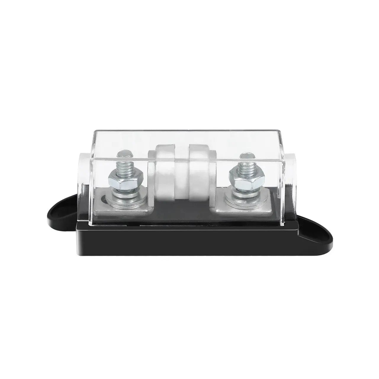 |
Supports up to 250V, with a V0‑rated flame‑retardant ABS polymer housing that reinforces safety protection. A built‑in stable fuse featuring arc‑extinguishing capability optimizes circuit protection, while ample space is reserved for larger cable packs and bolts. It is widely suitable for a variety of high‑current applications. |
| 1P DC Miniature Circuit Breaker | 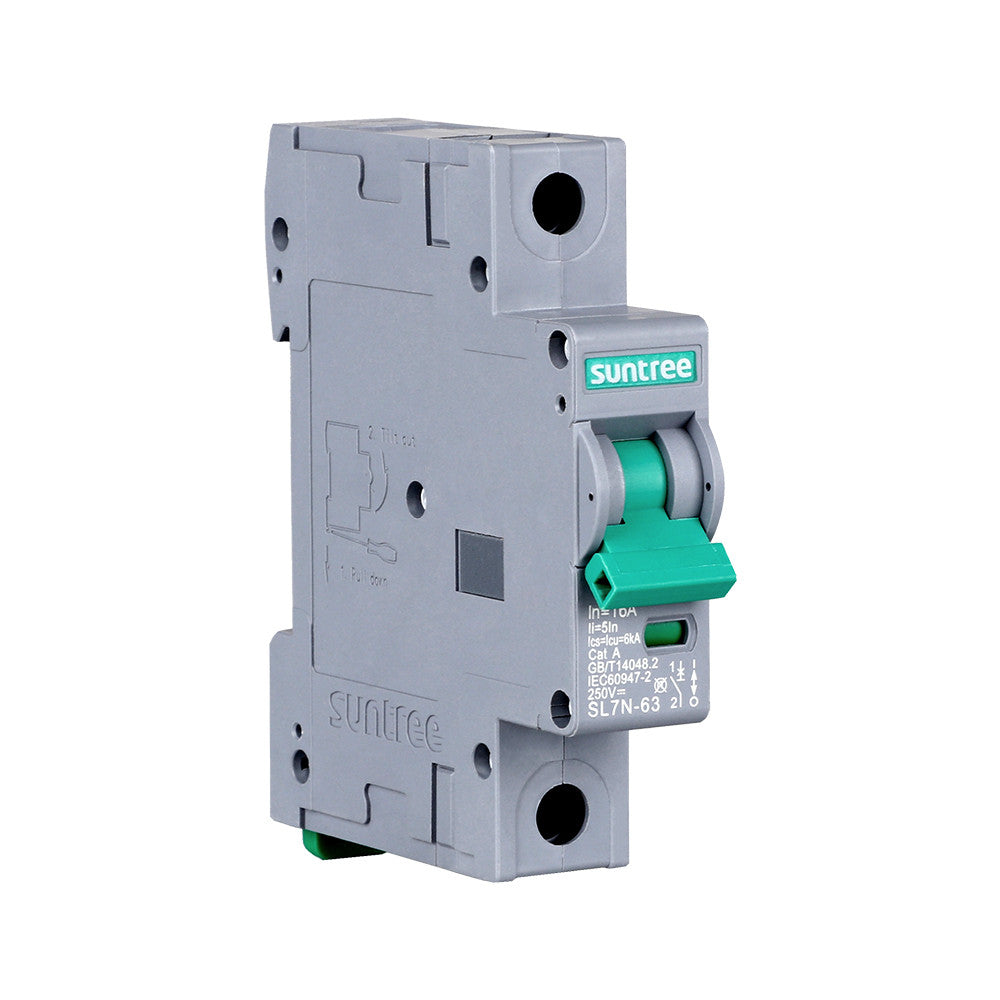 |
The Suntree DC Miniature Circuit Breaker is designed to protect DC electrical installations against overloads and short circuits with both the thermal and magnetic tripping mechanism equipped. Once a fault is detected, the circuit breaker automatically switches off the electrical circuit to prevent damage to wires and avoid the risk of fire. The circuit breaker can also be manually opened under the full rated load without any damage when electrical maintenance needs to be performed. Engineered for reversible connection, the circuit breaker is allowed to be wired in either direction and functions under bidirectional current. The built-in indicator window helps identify the contact position of the circuit breaker at a glance. The buckle design enables easy installation on the standard DIN rail. |


