


For specific design and application, please strictly follow current local electrical codes for proper selection and installation of protection devices. This guide is prepared based on ABYC E-11 and NEC standards; standards are updated periodically, please refer to the latest versions.
Why Wire Gauge Matters
Insufficient wire gauge leads to three serious consequences:
- Heating (fire risk): When current exceeds the conductor's rated ampacity, temperature rises, insulation may melt, causing short circuits and fire.
- Reduced efficiency: Power loss dissipates as heat, lowering system efficiency.
- Protection misoperation: Excessive voltage drop may trigger inverter low-voltage cutoff or charge controller misjudgment, preventing normal operation.
Why does voltage drop cause false alarms?
Taking an inverter as an example: inverters have low-voltage cutoff (LVC) protection, typically set at 10.5V (12V system). When a large load starts, the line voltage drop can cause the inverter input voltage to drop significantly below the actual battery voltage. Even if the battery is fully charged, the inverter may mistakenly shut down due to perceived low voltage. Similarly, a charge controller may exit maximum power point tracking prematurely due to lower sensed voltage.
Basic Cable Requirements (Applicable to All Scenarios)
Conductor standards:
- Material: Prefer tinned copper wire, especially in marine, coastal, and humid environments for significantly improved corrosion resistance. Never use copper-clad aluminum (CCA) cable — it has higher resistivity and is prone to oxidation and creep under vibration and moisture, a common cause of electrical fires.
- Construction: For RV/marine (vibration) applications, use stranded soft copper wire; solid copper wire is prohibited (fatigue fracture risk). For fixed buildings, follow local codes (THHN solid wire may be used).
- Certification & temperature rating: Prefer UL-listed 105°C (221°F) stranded soft copper wire; 90°C (194°F) is the next choice.
- Terminal temperature limitation: Even if the wire insulation is rated 105°C (221°F), if the equipment terminal/lug is only rated 75°C (167°F), the ampacity must be taken from the 75°C column. High-temperature wire does not automatically allow using the 105°C column for higher ampacity.
Fuse matching principle: The cable's maximum rated ampacity must be greater than the fuse rating to ensure that the fuse blows first under overcurrent, protecting the cable.
Voltage drop requirement: Recommended system voltage drop ≤ 3%.
Cable length: For voltage drop calculation, use the total length of positive and negative cables combined.
Wire Gauge Selection — Choose Based on Your Application
- RV/Marine (mobile vehicles, boats, etc.) → Jump to [RV/Marine — ABYC Standard]
- Residential/Fixed installation (homes, garages, commercial buildings, etc.) → Jump to [Residential/Fixed — NEC Standard]
Why distinguish between the two standards?
| Comparison Dimension | ABYC (American Boat & Yacht Council) | NEC (National Electrical Code) |
|---|---|---|
| Scope | Small vessels (yachts, boats), RV DC systems | Residential, commercial, industrial fixed buildings |
| Standard nature | Industry voluntary standard, widely regarded as best practice | Adopted as mandatory law in most states |
| Design philosophy | Focus on mobile/vibration/moisture/confined spaces; more stringent | Focus on fixed building installations; relatively stable heat dissipation |
| Ampacity basis | Based on engine room/cabin environment; more conservative derating factors | Based on fixed building environment; relatively relaxed derating factors |
| Typical applications | RV solar, marine electrical systems | Residential energy storage, balcony PV, commercial & industrial storage |
Why is ABYC recommended for RV/Marine DC systems?
- RVs and boats operate in vibration, moisture, and confined-space environments, requiring higher standards than fixed buildings.
- ABYC has more detailed and conservative ampacity derating requirements, with explicit rules for battery compartment ventilation, fire prevention, and explosion protection.
- In the RV/marine DC sector, mainstream equipment manufacturers design and certify to ABYC standards; following ABYC ensures better compatibility.
RV/Marine — ABYC Standard
Applicable scenarios: RV solar systems, marine electrical systems, campervans, towable RVs, and other mobile/vibration/moisture environments.
All sizing logic in this section is based on the American Boat & Yacht Council (ABYC) standard, widely regarded as industry best practice for mobile DC systems.
Vibration protection: In RV/marine environments, use locking washers or locknuts at all terminal connections and periodically check torque to prevent loosening and heating from vibration.
Corrosion resistance: For marine (saltwater) or coastal RV use, strongly recommend using tinned copper throughout and applying anti-oxidant conductive grease at all terminal connections.
1. ABYC Wire Gauge Quick Reference Table
Minimum wire size: Per ABYC E-11, except for signal circuits, the minimum allowable wire gauge for marine/RV DC power systems is 16 AWG. Do not go below this size.
Table notes:
- Current-carrying capacity basis, per ABYC E-11: insulation rating of 105°C (221°F) stranded copper conductors; single conductor routed in air (free air), outside the engine compartment; ambient temperature not to exceed 30°C (86°F).
- Voltage drop basis: for a 12V system, 3% voltage drop (0.36V); when the same wire gauge and current are used in a 24V system, the allowable length may be doubled (while still maintaining a 3% drop); for a 48V system, it may be quadrupled. Note: ampacity (current-carrying capacity) does not change with system voltage; the wire gauge must still be selected to meet the current requirements.
WARNING: Solid (single-strand) copper wire is strictly prohibited. In vibration-prone environments, solid conductors are susceptible to fatigue stress and may fracture, posing a safety hazard.
| Fuse rating (A) | 0–10 ft / 0–3 m | 10–15 ft / 3–4.5 m | 15–20 ft / 4.5–6 m | 20–28 ft / 6–8.5 m | 28–40 ft / 8.5–12 m | 40–50 ft / 12–15 m | 50–65 ft / 15–20 m |
|---|---|---|---|---|---|---|---|
| 0–20A | 12 AWG / 3.31 mm² | 10 AWG / 5.26 mm² | 8 AWG / 8.37 mm² | 8 AWG / 8.37 mm² | 6 AWG / 13.30 mm² | 4 AWG / 21.20 mm² | 4 AWG / 21.20 mm² |
| 20–30A | 10 AWG / 5.26 mm² | 8 AWG / 8.37 mm² | 6 AWG / 13.30 mm² | 6 AWG / 13.30 mm² | 4 AWG / 21.20 mm² | 3 AWG / 26.70 mm² | 2 AWG / 33.60 mm² |
| 30–50A | 8 AWG / 8.37 mm² | 6 AWG / 13.30 mm² | 4 AWG / 21.20 mm² | 4 AWG / 21.20 mm² | 2 AWG / 33.60 mm² | 1 AWG / 42.40 mm² | 1/0 AWG / 53.50 mm² |
| 50–80A | 6 AWG / 13.30 mm² | 4 AWG / 21.20 mm² | 3 AWG / 26.70 mm² | 2 AWG / 33.60 mm² | 1/0 AWG / 53.50 mm² | 2/0 AWG / 67.40 mm² | 3/0 AWG / 85.00 mm² |
| 80–105A | 4 AWG / 21.20 mm² | 3 AWG / 26.70 mm² | 2 AWG / 33.60 mm² | 1/0 AWG / 53.50 mm² | 2/0 AWG / 67.40 mm² | 3/0 AWG / 85.00 mm² | 4/0 AWG / 107.20 mm² |
| 105–140A | 4 AWG / 21.20 mm² | 2 AWG / 33.60 mm² | 1 AWG / 42.40 mm² | 2/0 AWG / 67.40 mm² | 3/0 AWG / 85.00 mm² | 4/0 AWG / 107.20 mm² | 300 kcmil / 152 mm² |
| 140–165A | 3 AWG / 26.70 mm² | 1 AWG / 42.40 mm² | 1/0 AWG / 53.50 mm² | 3/0 AWG / 85.00 mm² | 4/0 AWG / 107.20 mm² | 250 kcmil / 127 mm² | 350 kcmil / 177 mm² |
| 165–190A | 2 AWG / 33.60 mm² | 1 AWG / 42.40 mm² | 2/0 AWG / 67.40 mm² | 3/0 AWG / 85.00 mm² | 250 kcmil / 127 mm² | 300 kcmil / 152 mm² | 400 kcmil / 203 mm² |
| 190–220A | 1 AWG / 42.40 mm² | 1/0 AWG / 53.50 mm² | 2/0 AWG / 67.40 mm² | 4/0 AWG / 107.20 mm² | 300 kcmil / 152 mm² | 350 kcmil / 177 mm² | 500 kcmil / 253 mm² |
| 220–260A | 1/0 AWG / 53.50 mm² | 2/0 AWG / 67.40 mm² | 3/0 AWG / 85.00 mm² | 4/0 AWG / 107.20 mm² | 300 kcmil / 152 mm² | 400 kcmil / 203 mm² | 500 kcmil / 253 mm² |
| 260–300A | 2/0 AWG / 67.40 mm² | 3/0 AWG / 85.00 mm² | 4/0 AWG / 107.20 mm² | 250 kcmil / 127 mm² | 350 kcmil / 177 mm² | 500 kcmil / 253 mm² | 600 kcmil / 304 mm² |
| 300–350A | 3/0 AWG / 85.00 mm² | 4/0 AWG / 107.20 mm² | 4/0 AWG / 107.20 mm² | 300 kcmil / 152 mm² | 500 kcmil / 253 mm² | 600 kcmil / 304 mm² | — |
| 350–405A | 4/0 AWG / 107.20 mm² | 4/0 AWG / 107.20 mm² | 250 kcmil / 127 mm² | 350 kcmil / 177 mm² | 500 kcmil / 253 mm² | 600 kcmil / 304 mm² | — |
| 405–450A | 250 kcmil / 127 mm² | 250 kcmil / 127 mm² | 300 kcmil / 152 mm² | 400 kcmil / 203 mm² | 600 kcmil / 304 mm² | — | — |
2. ABYC Derating & Special Considerations
2.1 Ambient Temperature Derating (Engine Compartment / High Temperature)
ABYC E-11 defines different ampacity derating factors based on the ambient temperature of the installation area. For common 105°C (221°F) insulated conductors, ABYC classifies areas into two categories with different temperature factors:
| Installation Area | Temperature Factor | Typical Scenario |
|---|---|---|
| Outside Engine Spaces | 1.00 | Cabin, storage, helm, etc. – normal temperature areas |
| Inside Engine Spaces | 0.85 | Engine room, generator room, boiler room – high temperature areas |
ABYC E-11 requires: if any segment of a conductor passes through an engine space, the entire conductor must be derated using the engine-space factor (0.85), not just the engine-space segment.
How to understand and apply temperature factors:
- Define "engine space": In ABYC, "Engine Spaces" typically refers to areas where the ambient temperature is 20°C (36°F) higher than outside. For RVs, this can be considered the engine compartment or generator compartment — any notably high-temperature area.
-
Application method:
- Conductor routed outside engine spaces: temperature factor = 1.00, no derating needed.
- Conductor routed inside engine spaces: temperature factor = 0.85, ampacity must be multiplied by 0.85.
Available ampacity inside engine space = Base ampacity (1. quick table) × 0.85
- Combined derating: If a conductor is both "inside engine space" and "bundled (more than 2 conductors)", the derating factors are multiplied together.
- Standard updates: ABYC standards are updated periodically. For critical designs, consult the latest official standard.
ABYC temperature derating selection example:
Assume an RV DC circuit with fuse rating 30A. The conductor must run from the cabin through the engine compartment to the battery. Use 105°C (221°F) insulated copper, with 4 conductors bundled in the engine compartment:
| Step | Calculation | Result |
|---|---|---|
| From quick table for 30A (13–18 ft range) | 30A corresponds to 10 AWG | 10 AWG base ampacity = 60A |
| Engine space temperature factor | 60A × 0.85 | 51.0A |
| Bundling derating (4–6 conductors) | 51.0A × 0.80 | 40.8A |
| Final available ampacity | 40.8A ≥ 30A | ✓ Satisfied |
2.2 Bundling Derating
When multiple conductors are bundled together (more than 2 current-carrying conductors), heat dissipation worsens. Apply additional derating per ABYC E-11:
| Number of current-carrying conductors bundled | Derating factor |
|---|---|
| 1–3 | 1.00 |
| 4–6 | 0.80 |
| 7–15 | 0.70 |
| 16–30 | 0.50 |
Final available ampacity = Base ampacity (1. quick table) × Temperature factor (1.00 or 0.85) × Bundling derating factor
|
NOTE
The above data are based on ABYC E-11 for 105°C (221°F) insulated conductors. For other temperature ratings, consult the appropriate standard. |
Residential/Fixed Installation — NEC Standard
Applicable scenarios: Residential energy storage, balcony PV, garages, commercial buildings, ground-mounted systems — fixed installations.
All sizing logic in this section is based on the US National Electrical Code (NEC).
1. Choose the Correct NEC Ampacity Table Based on Installation Method
NEC provides different ampacity tables based on the conductor's heat dissipation conditions. Select based on actual installation:
| Installation Scenario | NEC Table | Description |
|---|---|---|
| Raceway, Cable, Directly Buried | Table 310.16 | Most common scenario. Applies to conductors in conduit, cable trays, or directly buried. This table assumes no more than 3 current-carrying conductors. |
| Free Air | Table 310.17 | Applies to conductors installed in open air where air can circulate freely, e.g., overhead lines, open cable trays. Better heat dissipation — ampacity is significantly higher than raceway for the same gauge. |
Critical reminders:
- Table 310.16 is the default: Unless the conductor is explicitly installed in "Free Air", use Table 310.16.
- "Free Air" is strictly defined: It means an open or ventilated environment that allows heat dissipation and air circulation around the conductor. Conductors inside closed electrical boxes or control cabinets cannot use Table 310.17.
- Wrong usage has serious consequences: Using the higher ampacity from Table 310.17 for raceway-installed conductors leads to undersized wires and creates a serious fire hazard.
2. Determine the Ampacity Column Based on Equipment Terminal Temperature
After choosing the correct table, select the correct temperature column.
- Rule (NEC 110.14(C)): The final ampacity of a conductor must not exceed the lowest temperature rating of any component in the circuit — typically the equipment terminals (breakers, lugs, etc.).
- Recommendation: Check the terminal temperature marking on the equipment. If no marking, using the 60°C (140°F) column is a safe and conservative choice.
3. Apply Correction and Adjustment Factors
The base ampacity from Table 310.16 or 310.17 must then be corrected:
- Ambient temperature correction (NEC Table 310.15(B)(1)): Multiply by the correction factor if ambient temperature differs from 30°C (86°F).
- Multiple conductor adjustment (NEC Table 310.15(C)(1)): When more than 3 current-carrying conductors are bundled together or in the same cable/conduit for more than 24 inches (≈60 cm), multiply by the adjustment factor.
Actual available ampacity = Base ampacity × Temperature correction factor × Multiple conductor adjustment factor
4. NEC 240.4(D) Small Conductor Overcurrent Protection Mandatory Limit
After applying temperature and adjustment factors, you must also check NEC 240.4(D) for small conductors.
NEC defines conductors 18 AWG through 10 AWG as "small conductors". 240.4(D) limits the maximum rating of the overcurrent protection device (fuse or breaker), not the conductor ampacity itself. In other words, even if a conductor has a higher ampacity in Table 310.16 (e.g., 10 AWG copper at 75°C = 35A), the overcurrent device rating must not exceed the 240.4(D) limit.
Small conductor overcurrent protection limits for copper (NEC 240.4(D)):
| Wire gauge (AWG) | Maximum overcurrent device rating |
|---|---|
| 18 AWG | 7A |
| 16 AWG | 10A |
| 14 AWG | 15A |
| 12 AWG | 20A |
| 10 AWG | 30A |
Three rules apply simultaneously:
Final selection must satisfy all three conditions:
- Ampacity constraint: Actual available ampacity ≥ load current × 1.25 (for continuous loads)
- 240.4(D) upper limit: Fuse/breaker rating ≤ the limit for that gauge
- 240.4(B) does not apply: The "round up to next standard size" rule does not apply to small conductors (18–10 AWG)
Important notes:
Exceptions: 240.4(E) and 240.4(G) list a few exceptions (e.g., specific tap conductors, motor circuits) where 240.4(D) may not apply. For the typical PV/energy storage DC systems covered in this guide, these exceptions generally do not apply. For special circuits, a qualified electrical engineer should make a professional judgment per NEC.
Relationship to ampacity tables: The 240.4(D) limit is a mandatory upper limit independent of the ampacity table. The correct selection process is:
- Find base ampacity from Table 310.16/310.17.
- Apply temperature and adjustment factors to get actual available ampacity.
- Actual available ampacity must be ≥ load current × 1.25 (continuous load).
- At the same time, the fuse/breaker rating must not exceed the 240.4(D) limit.
240.4(B) "round up" does not apply to small conductors: 240.4(D) is an absolute upper limit — even if the corrected ampacity is higher (e.g., 14 AWG corrected to 19A in a cool environment), the overcurrent device rating must not exceed 15A.
Selection example: Assume a 12 AWG copper conductor (75°C insulation) installed in raceway, continuous load 14A (×1.25 = 17.5A), ambient temperature 45°C (113°F), with 4 current-carrying conductors in the same conduit:
| Step | Calculation | Result |
|---|---|---|
| Base ampacity (Table 310.16, 75°C) | 12 AWG | 25A |
| Temperature correction (45°C / 113°F, 75°C insulation) | 25A × 0.82 | 20.5A |
| Multiple conductor adjustment (4 conductors, 0.80) | 20.5A × 0.80 | 16.4A |
| Ampacity constraint | 16.4A ≥ 17.5A? | Not satisfied — must increase gauge! |
| 240.4(D) limit | 12 AWG copper | Max 20A |
Initially, the conductor fails to meet the ampacity requirement because its ampacity (16.4 A) is below the load current (17.5 A), so a larger size must be selected. When 10 AWG is tried, its base ampacity of 35 A (from the 75°C column) is adjusted by the correction factors 0.82 and 0.80, yielding 22.96 A, which is well above the 17.5 A load, thus satisfying the ampacity condition. However, NEC Section 240.4(D) limits the overcurrent protection device for 10 AWG conductors to a maximum rating of 30 A; therefore, the final choice is a fuse or circuit breaker rated at either 25 A or 30 A (depending on available standard ratings), but never exceeding 30 A, while still being sufficient for the load current.
5. Calculate Voltage Drop
After ampacity is satisfied, ensure voltage drop does not exceed 3%.
Voltage drop basis: This guide uses 12V system as the basis. For 24V, length can be 2×; for 48V, 4×.
Voltage Drop Calculation
Formula
Vdrop (V) = (2 × L × I × R) / 1000
Definitions
- L = one‑way conductor length (ft)
- I = load current (A)
- R = conductor resistance (Ω per 1000 ft)
Copper Wire Resistance Reference (Ω / 1000 ft)
| AWG | Resistance (Ω / 1000 ft) |
|---|---|
| 10 | 1.0 |
| 8 | 0.628 |
| 6 | 0.395 |
| 4 | 0.249 |
| 2 | 0.156 |
| 1/0 | 0.098 |
| 2/0 | 0.078 |
| 4/0 | 0.049 |
Voltage Drop Percentage
%Vdrop = (Vdrop / System Voltage) × 100%
Worked Example
- System voltage = 12 V
- Wire gauge = 10 AWG (R = 1.0 Ω / 1000 ft)
- One‑way length = 15 ft
- Current = 20 A
Step 1 – Calculate voltage drop:
Vdrop = (2 × 15 × 20 × 1.0) / 1000 = 0.60 V
Step 2 – Calculate percentage:
%Vdrop = (0.60 / 12) × 100% = 5.0%
Step 3 – Decision:
5.0% exceeds the typical 3% limit → increase wire gauge (use a thicker conductor).
6. NEC Copper Conductor Ampacity Quick Reference
6.1 Copper Ampacity (NEC Table 310.16) — Raceway / Cable / Direct Buried
Table notes: Based on NEC Table 310.16, no more than 3 current-carrying conductors, ambient 30°C (86°F), copper base ampacity (amperes).
| Wire gauge (AWG/kcmil) | 60°C (140°F) | 75°C (167°F) | 90°C (194°F) |
|---|---|---|---|
| 18 | — | — | 14 |
| 16 | — | — | 18 |
| 14 | 15 | 20 | 25 |
| 12 | 20 | 25 | 30 |
| 10 | 30 | 35 | 40 |
| 8 | 40 | 50 | 55 |
| 6 | 55 | 65 | 75 |
| 4 | 70 | 85 | 95 |
| 3 | 85 | 100 | 115 |
| 2 | 95 | 115 | 130 |
| 1 | 110 | 130 | 145 |
| 1/0 | 125 | 150 | 170 |
| 2/0 | 145 | 175 | 195 |
| 3/0 | 165 | 200 | 225 |
| 4/0 | 195 | 230 | 260 |
| 250 kcmil | 215 | 255 | 290 |
| 300 kcmil | 240 | 285 | 320 |
| 350 kcmil | 260 | 310 | 350 |
| 400 kcmil | 280 | 335 | 380 |
| 500 kcmil | 320 | 380 | 430 |
Note: For 18 AWG and 16 AWG, Table 310.16 lists only 90°C values (14A and 18A). However, per NEC 240.4(D), the overcurrent device limits are 7A and 10A respectively — these are mandatory absolute limits.
6.2 Copper Ampacity (NEC Table 310.17) — Free Air
Table notes: Based on NEC Table 310.17, for conductors installed in free air.
| Wire gauge (AWG/kcmil) | 60°C (140°F) | 75°C (167°F) | 90°C (194°F) |
|---|---|---|---|
| 18 | — | — | 24 |
| 16 | — | — | 30 |
| 14 | 20 | 25 | 30 |
| 12 | 25 | 30 | 35 |
| 10 | 40 | 50 | 55 |
| 8 | 55 | 70 | 80 |
| 6 | 80 | 95 | 105 |
| 4 | 105 | 125 | 140 |
| 3 | 120 | 145 | 165 |
| 2 | 140 | 170 | 190 |
| 1 | 165 | 195 | 220 |
| 1/0 | 195 | 230 | 260 |
| 2/0 | 225 | 265 | 300 |
| 3/0 | 260 | 310 | 350 |
| 4/0 | 300 | 360 | 405 |
| 250 kcmil | 340 | 405 | 455 |
| 300 kcmil | 375 | 445 | 505 |
| 350 kcmil | 420 | 505 | 570 |
| 400 kcmil | 455 | 545 | 615 |
| 500 kcmil | 515 | 620 | 700 |
Note: Even in free air, small conductors 18–10 AWG are still subject to NEC 240.4(D) overcurrent device limits.
6.3 Ambient Temperature Correction Factors (NEC Table 310.15(B)(1))
Usage: Base ampacity × factor = actual allowable ampacity at that temperature.
| Ambient °C | Ambient °F | 60°C insulation | 75°C insulation | 90°C insulation |
|---|---|---|---|---|
| 21–25 | 70–77 | 1.08 | 1.05 | 1.04 |
| 26–30 | 78–86 | 1.00 | 1.00 | 1.00 |
| 31–35 | 87–95 | 0.91 | 0.94 | 0.96 |
| 36–40 | 96–104 | 0.82 | 0.88 | 0.91 |
| 41–45 | 105–113 | 0.71 | 0.82 | 0.87 |
| 46–50 | 114–122 | 0.58 | 0.75 | 0.82 |
| 51–55 | 123–131 | 0.41 | 0.67 | 0.76 |
| 56–60 | 132–140 | — | 0.58 | 0.71 |
| 61–65 | 141–149 | — | 0.47 | 0.65 |
| 66–70 | 150–158 | — | 0.33 | 0.58 |
| 71–75 | 159–167 | — | — | 0.50 |
| 76–80 | 168–176 | — | — | 0.41 |
| 81–85 | 177–185 | — | — | 0.29 |
6.4 Multiple Current-Carrying Conductor Adjustment Factors (NEC Table 310.15(C)(1))
Usage: When more than 3 current-carrying conductors are bundled or in the same cable/conduit for more than 24 inches (≈60 cm), multiply base ampacity by the factor.
| Number of current-carrying conductors in same cable/conduit | Adjustment factor |
|---|---|
| 1–3 | 1.00 |
| 4–6 | 0.80 |
| 7–9 | 0.70 |
| 10–20 | 0.50 |
| 21–30 | 0.45 |
| 31–40 | 0.40 |
| 41 and above | 0.35 |
7. Complete NEC Selection Workflow Example
Scenario: 12V system, continuous load 14A (fuse must be ≥ 14A × 1.25 = 17.5A). Conductors installed in raceway, ambient temperature 45°C (113°F), 4 current-carrying conductors in same conduit, 75°C insulation copper.
Step 1: Initial Gauge Selection by Ampacity
Try 12 AWG (75°C column ampacity 25A):
- Temperature correction (45°C): 25A × 0.82 = 20.5A
- Adjustment for 4 conductors: 20.5A × 0.80 = 16.4A
Check: 16.4A ≥ 17.5A? No → increase gauge.
Try 10 AWG (75°C column 35A):
- 35A × 0.82 × 0.80 = 22.96A ≥ 17.5A ✓ (ampacity satisfied)
Step 2: Check 240.4(D) Limit
For 10 AWG copper, the maximum overcurrent protection rating is 30A (per NEC 240.4(D)).
Step 3: Final Gauge and Overcurrent Protection Device
Wire gauge: 10 AWG.
Overcurrent protection rating: Must be at least 17.5A (load requirement). It should not exceed the corrected ampacity (22.96A) unless using the next higher standard rating allowed by 240.4(B). Standard ratings: 15A, 20A, 25A, 30A.
- 20A is ≤22.96A and ≥17.5A → acceptable.
- 25A is the next higher standard rating above 22.96A (since 22.96 is not a standard rating), so 240.4(B) permits 25A. This is the recommended choice to provide margin.
- 30A exceeds 22.96A and is not the next higher (the next higher is 25A), so 30A is not permitted even though it is the 240.4(D) maximum. Do not select 30A.
Recommended fuse/breaker: 25A (or 20A as a conservative option). Must not exceed 30A, but 30A itself is not a valid choice here.
Step 4: Check Voltage Drop
Assume total length (positive + negative) = 30 ft (~9 m). Calculate voltage drop separately for 12V system; ensure it is ≤ 3%.
Solar Panel Special-Purpose Cable Selection
PV wires with MC4 connectors available on the market are typically 12 AWG / 4 mm² or 10 AWG / 6 mm².
1. Connector Current Rating Limit
MC4-type PV connectors typically have a current rating of 30A (some models 20A) — this is a hard upper limit for branch current. Always follow the connector datasheet and leave 20% margin.
- Total current ≤ connector rating: Can use Y-branch connectors for parallel connection.

- Total current > connector rating: Must use a combiner box or busbar for parallel connection, then use a larger-gauge main cable to connect to the energy equipment. Install an additional main fuse at the combined output — fuse rating = total current × 1.25, round up.

2. Cable Standards
Must use weather-resistant, UV-resistant PV cables certified to local codes.
- North America: Use PV Wire or USE-2 type cable.
- Europe: Use PV1-F or EN 50618 H1Z2Z2-K type cable.
Bending radius: Minimum bending radius ≥ 4–6× cable outer diameter; refer to cable datasheet for exact value.
3. Solar Panel Special-Purpose Cable Quick Reference
Notes: Based on copper PV cable (90°C / 194°F), DC voltage drop ≤ 3%, ambient ≤ 40°C (104°F). Table upper limit is 60A; above this, combine via combiner/busbar and refer to the main gauge tables.
If the ambient temperature exceeds 40°C / 104°F, the ampacity must be adjusted according to the correction factors in NEC 310.15(B) (for example, for 90°C / 194°F insulation at 40°C / 104°F ambient, the correction factor is 0.91, ~9% derating). When multiple cables are run in conduit, the ampacity must be further derated by 15%–25%. For more precise calculations, refer to the NEC 310.16 ampacity tables (US) or CSA C22.1 Tables 2/4/5 (Canada).
| Fuse current | Cable length | Recommended gauge |
|---|---|---|
| 0–10A | 0–5m / 0–16.4ft | 12 AWG / 3.31 mm² |
| 10–20A | 0–8m / 0–26.2ft | 10 AWG / 5.26 mm² |
| 20–30A | 0–10m / 0–32.8ft | 8 AWG / 8.37 mm² |
| 30–40A | 0–12m / 0–39.4ft | 6 AWG / 13.30 mm² |
| 40–50A | 0–15m / 0–49.2ft | 4 AWG / 21.20 mm² |
| 50–60A | 0–18m / 0–59.1ft | 3 AWG / 26.70 mm² |
Important reminder (NEC 240.4(D) applies to PV DC side):
- In the quick table above, if the final wire gauge is 14 AWG, 12 AWG, or 10 AWG, the fuse rating is also subject to NEC 240.4(D) mandatory upper limits: 15A, 20A, and 30A respectively.
- Even if the table suggests a higher fuse rating, do not exceed the 240.4(D) upper limit.
Example:
- For the 20–30A load current range, the table recommends 8 AWG. Since 8 AWG is not a "small conductor" (≥8 AWG is exempt from 240.4(D)), normal ampacity-based selection applies.
- For the 10–20A load current range, the table recommends 10 AWG. Even if ampacity would allow a 25A fuse, 240.4(D) strictly limits 10 AWG to 30A maximum, and 12 AWG to 20A maximum.
Cable Purchase Links
You can purchase appropriately rated cables from the Renogy official website (select as needed):
| Product Name | Image | Description |
|---|---|---|
| Battery to Charge Controller Tray Cables for 3/8 in Lugs | 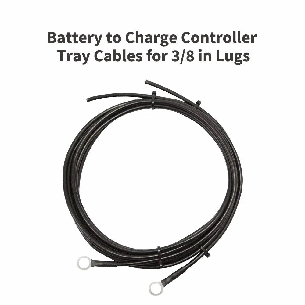 |
A complete cable set specifically for connecting the charge controller to the battery. One end of this cable has 3/8‑inch ring terminals for easy connection to battery terminals; the other end has stripped wires for direct connection to the charge controller. The cable is made of tinned pure copper, offering excellent conductivity and corrosion resistance, and is a core component for connecting energy storage devices. |
| ANL Fuse Cable with Double Ring Terminals for 3/8 in Lugs | 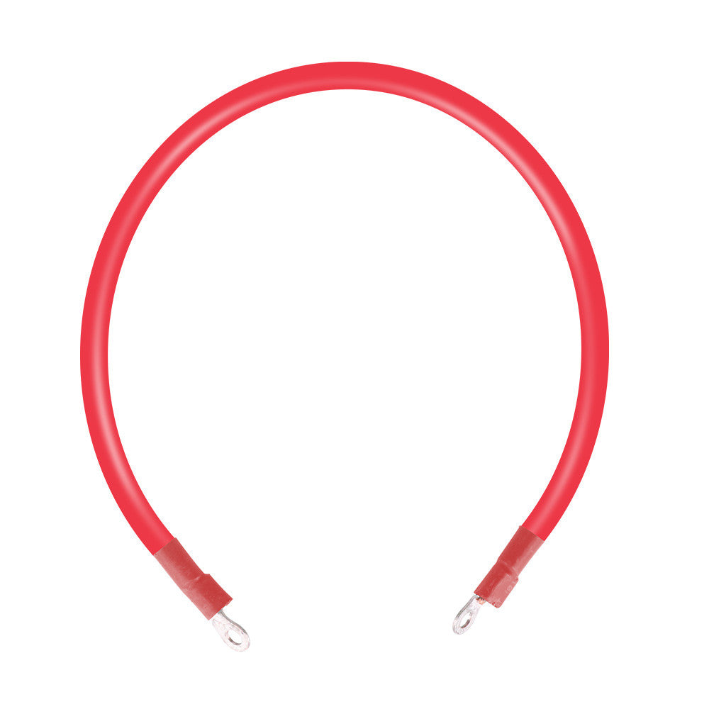 |
The cable required for installing an ANL fuse. This fuse cable is made for connecting your ANL fuse to your batteries. It is specialized with battery rings on both ends — one for effortless connection to the battery and the other for effortless connection to the ANL fuse. |
| Copper Battery Interconnect Cable for 5/16 in Lugs | 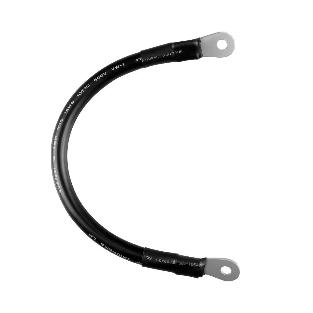 |
Connect your batteries in series (×1) or parallel (×2) with the Renogy high-quality battery cables. Specialized with 5/16'' tin-plated copper lugs on both ends, it provides abrasion resistance and electrical safety for your system. |
| Battery Inverter Cables for 3/8 in Lugs | 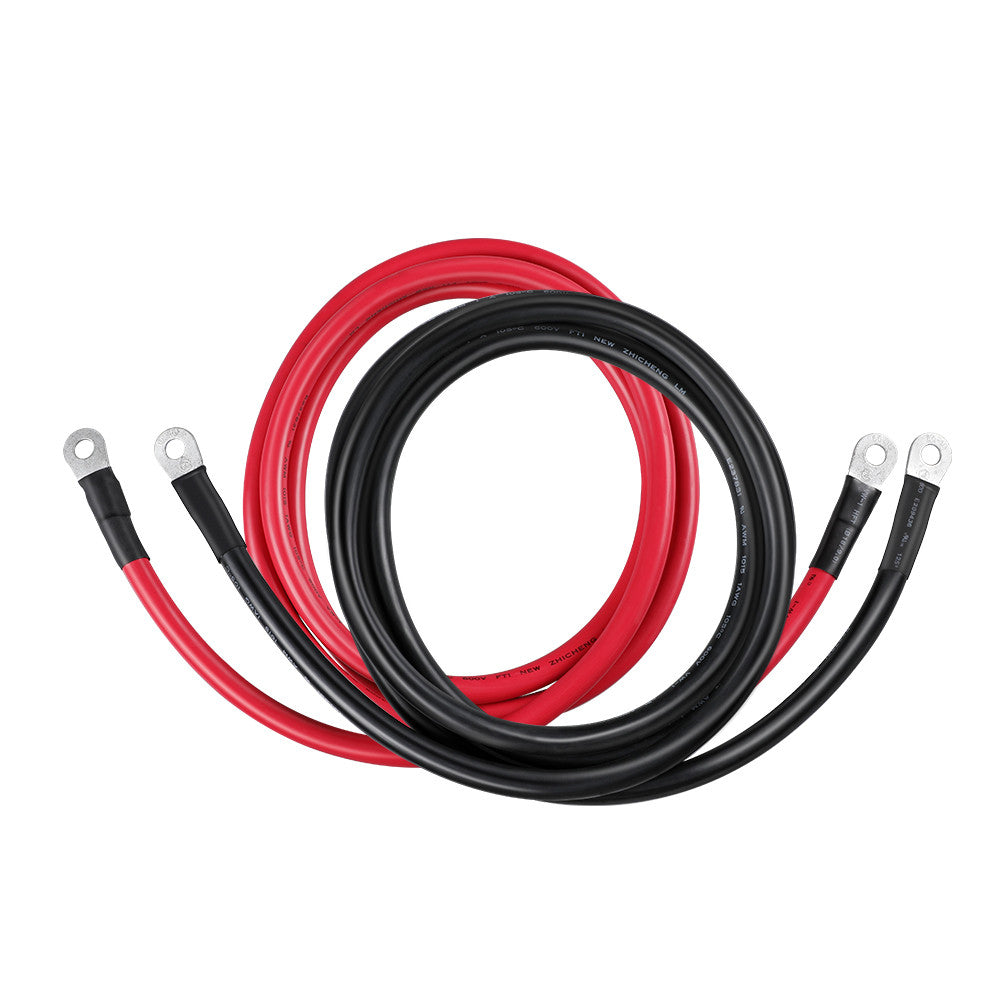 |
Designed to be used between a power inverter and a battery bank, the Inverter Cables are made of UL-certified Cobra X-Flex, making them resistant to moisture, abrasion, acid, diesel fuel, and oil. Color-coded for easy identification, these cables have heat shrink on both ends and feature stainless steel ring terminals that use 3/8 lugs. Match this pair of inverter cables with your inverter for a secure connection to your battery bank. |
| Solar Panel Extension Cable with Male to Female Solar Connectors | 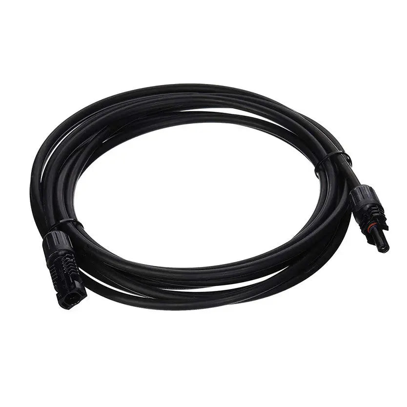 |
Extends the connection distance between the solar panel and the charge controller, or between two solar panels. This extension cable provides greater flexibility in system layout, allowing users to position components according to actual installation space requirements. The cable is TUV‑certified, UV‑resistant, and waterproof, ensuring safety and reliability in outdoor environments. |
| Solar Panel to Charge Controller Adaptor Kit | 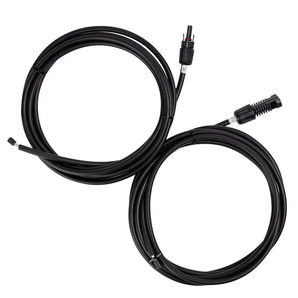 |
A complete cable set specifically for connecting solar panels to the charge controller. This adapter cable has solar connectors (male and female) on one end for direct plug‑in to the solar panel, and stripped wires on the other end for direct connection to the charge controller. It is an essential wiring component for off‑grid solar system installation, saving users the trouble of making their own cables. |
| Solar Connector to SAE Adapter 12 AWG Cable | 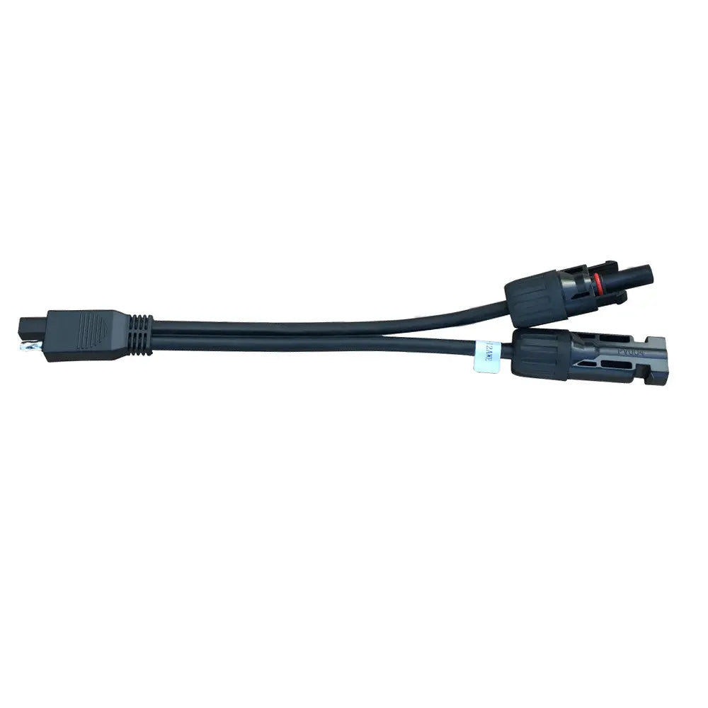 |
Our new Solar Connector to SAE Adapter is perfect for those trying to wire SAE solar ready RVs. These connectors come in 12 AWG and are just over 10.5 inches long. These connections are perfect for hooking up your Renogy solar suitcase or panels to your RV. Make going solar easy with the Solar Connector to SAE Adapter! |
| Solar Y Branch Connectors MMF+FFM Pair | 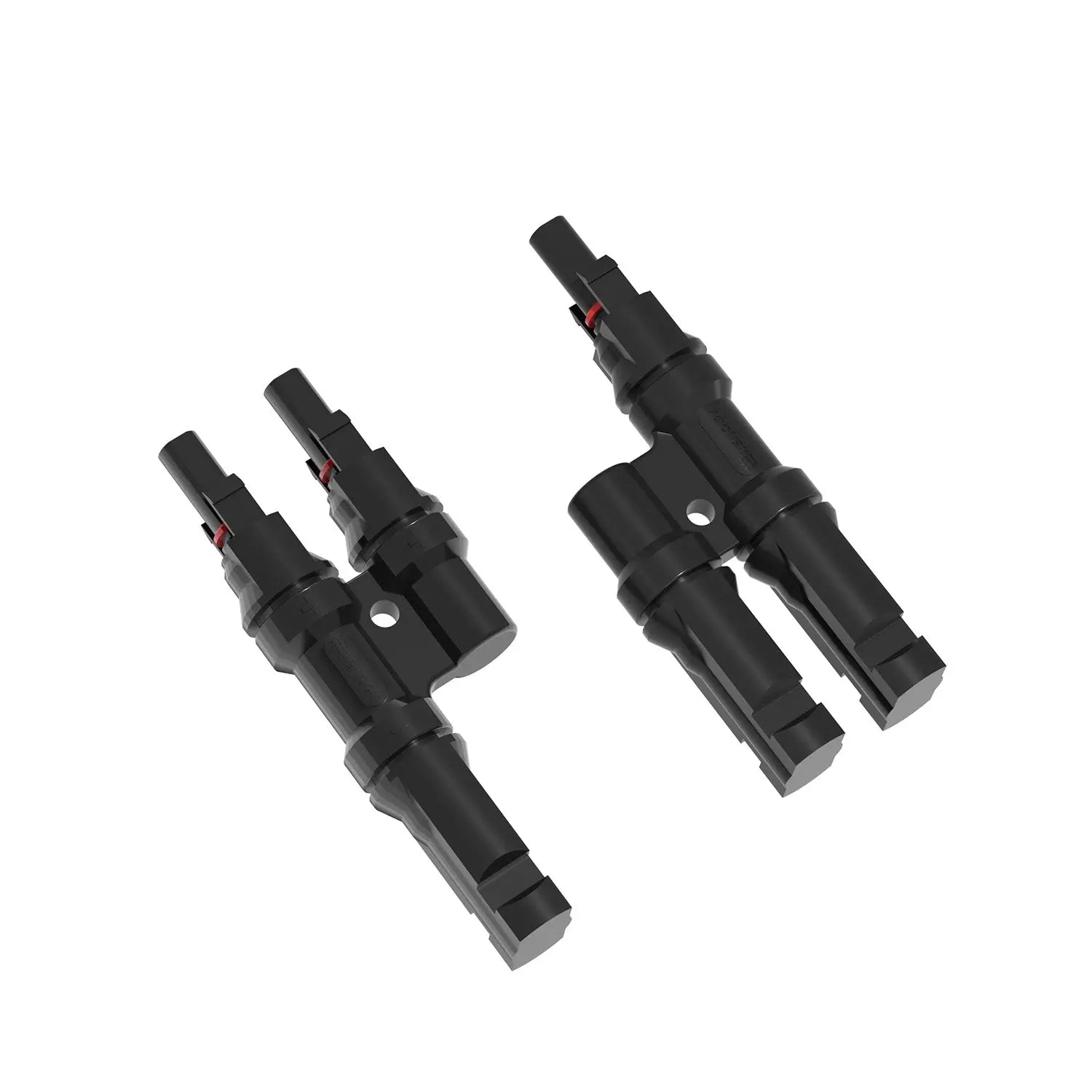 |
Solar Y Branch Connectors are used for parallel wiring solar panels (PV modules). Sold as a pair, these "Y-Connectors" will maintain the voltage of the solar panel configuration to match the battery size. These connectors are solely compatible with Solar connectors and come with one male (MMF) and one female (FFM) connector. Use these Solar Branch Connectors to make tight, waterproof connections. |
| 3 to 1 Solar Branch Connectors MMMF+FFFM Pair | 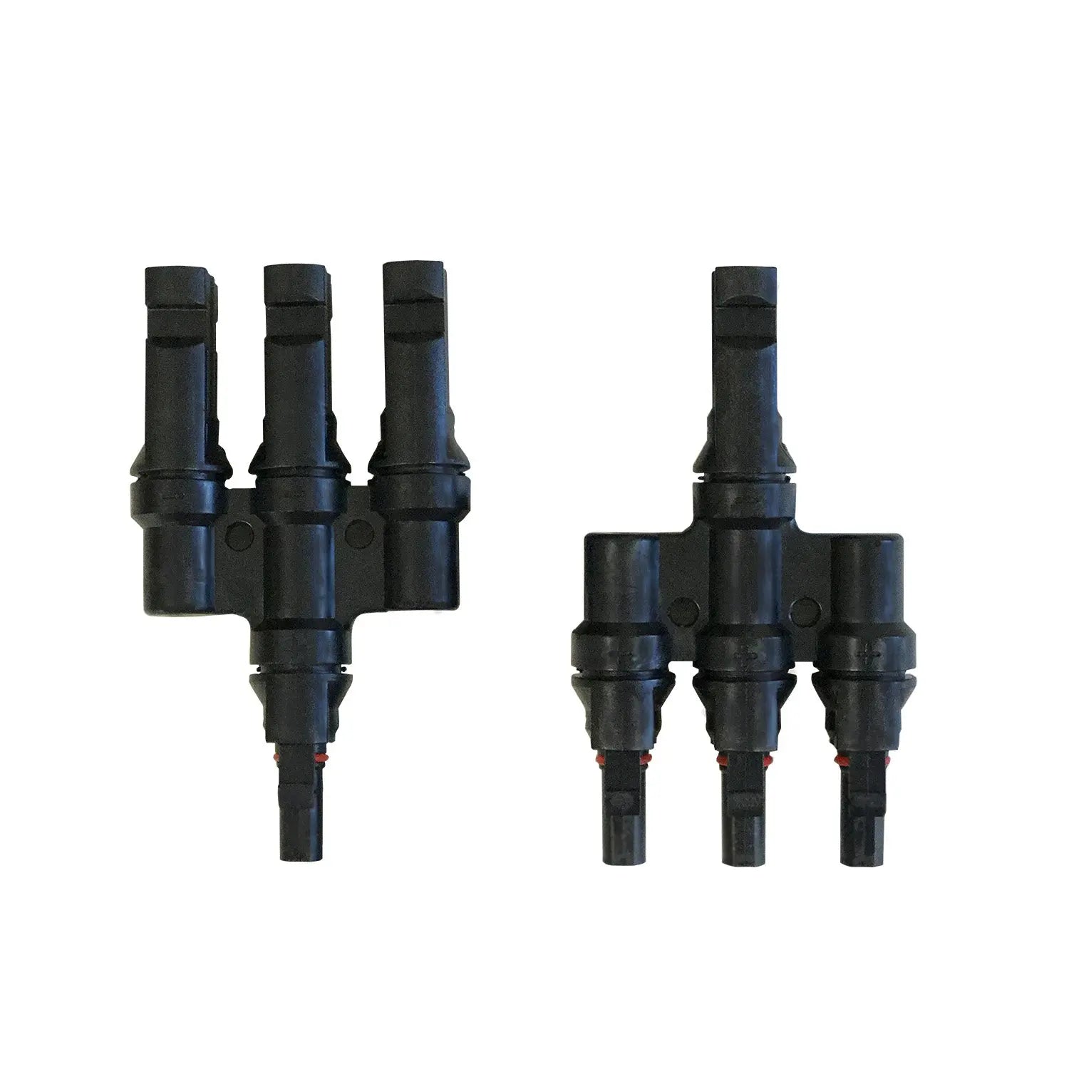 |
The Limited Branch Connector is a perfect solution for connecting three panels in parallel. These connectors have high aging resistance and UV endurance, making them weather-proof and able to withstand harsh environments. A rivet and lock are used to connect the cable and no extra tools are required for assembly or disassembly of plugs. |
| Solar Connectors Y Branch Parallel Adapter Cable MMF+FFM Pair | 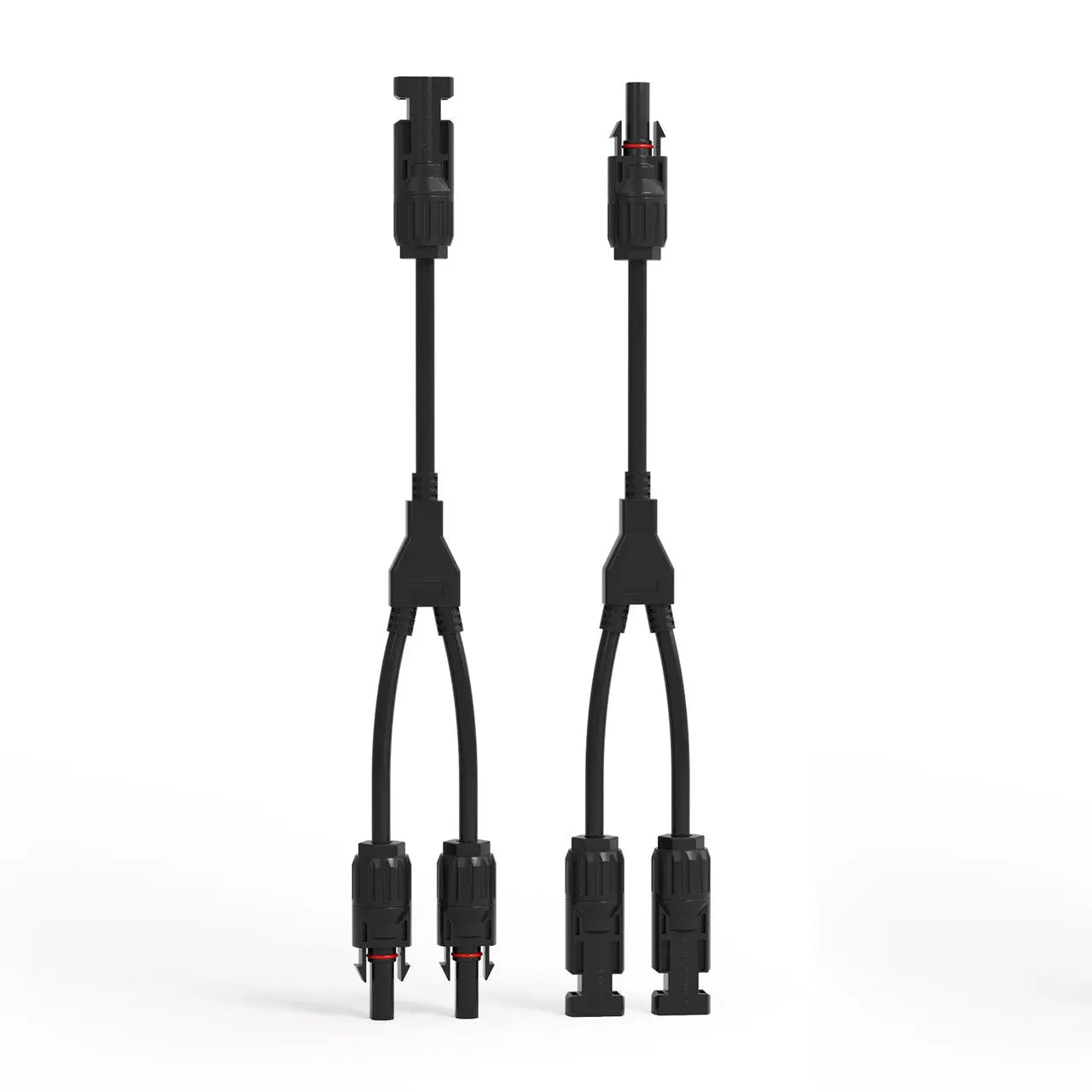 |
TUV & CE certification. PC material with resistance to oils and high temperature. IP67 protection. Compatible with 14AWG - 10AWG (2.5mm² - 6mm²) solar cables. Effortless setup by pressing the built-in lock on the male connector. |
| 4 to 1 Solar Branch Connectors MMMMF+FFFFM Pair | 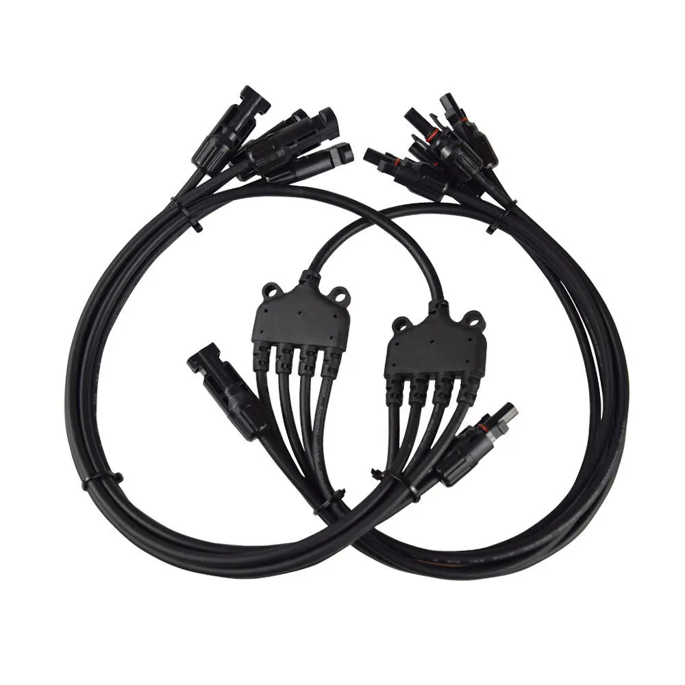 |
Make wiring parallel solar panels a breeze with these extended 4 to 1 Solar Branch connectors. Primarily suitable for 400W kits, these connectors allow you to install panels in portrait or landscape orientations without the messy wires in your way. Each package comes in pairs. |
| Solar Connectors for Solar Panels 5 Pairs Male & Female | 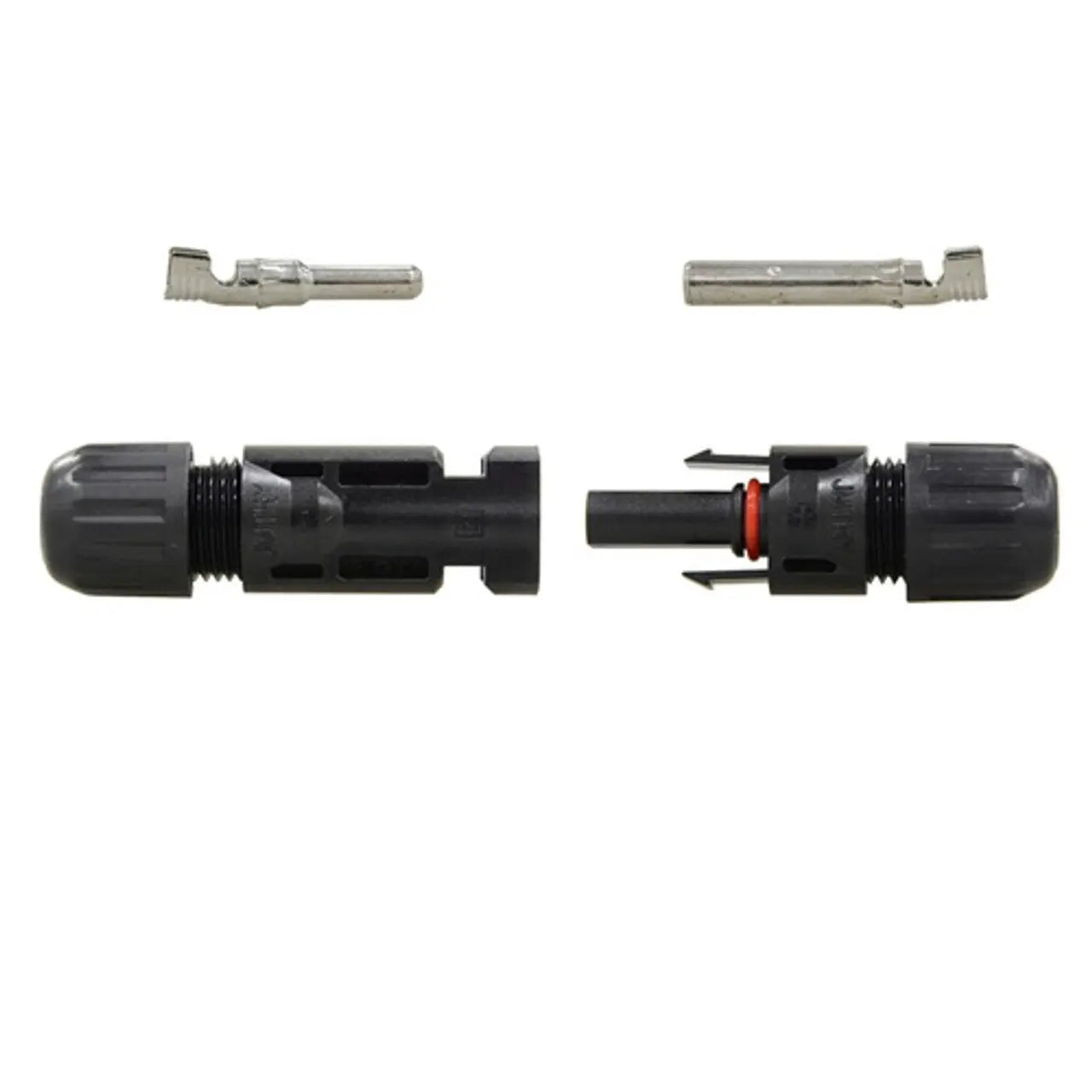 |
This connector is specifically designed for connecting photovoltaic solar systems with high mechanical requirements and extreme weather conditions. For permanent installations. Renogy Solar Cable Connectors are made with highest quality materials. They are both heavier and sturdier than many other brands, ensuring long term reliability and performance. These connectors are designed to complete a solar panel (PV) array, typically in parallel applications. These connectors are also waterproof and resist dust build up. |
| Solar Connector Assembly Tool | 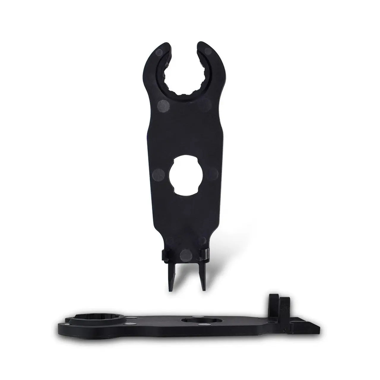 |
The Solar Connector Assembly Tool is a hard plastic material that is very handy for both the assembly of custom solar connector wires, making it easier for new and veteran users to quickly and easily tighten and take apart the connectors. |
| DC Circuit Breaker Box | 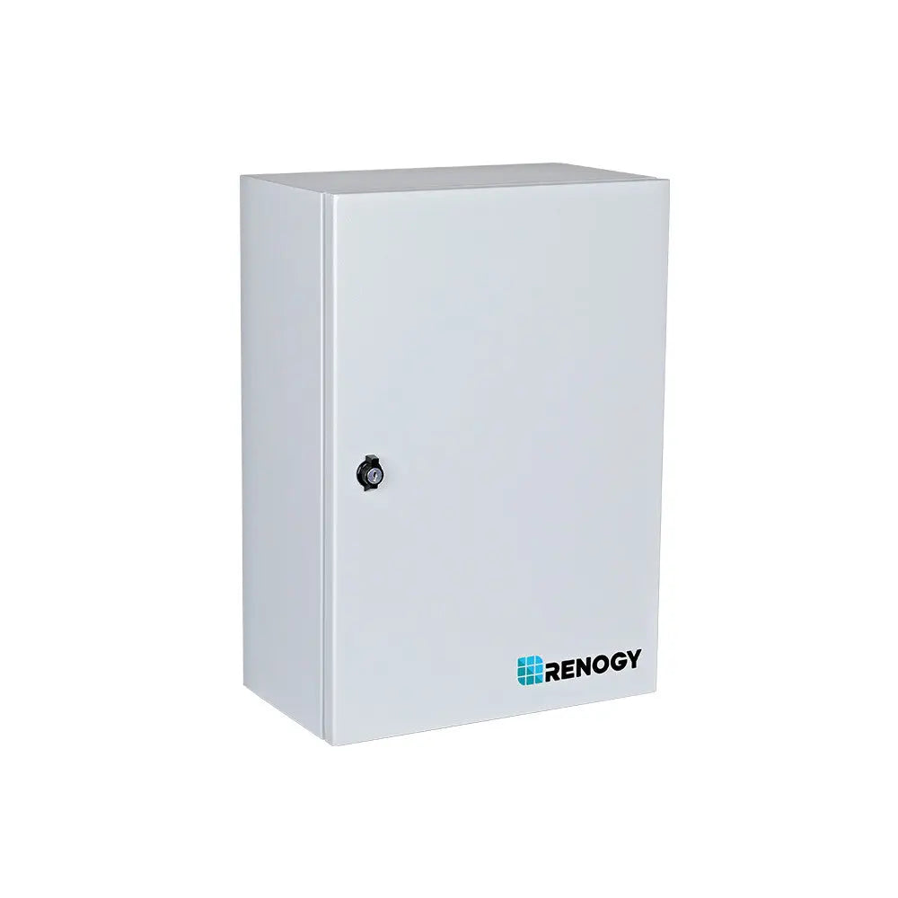 |
The Renogy DC Circuit Breaker Box is an indoor-rated enclosure that offers centralized installation and protection for devices in the residential and commercial solar system. For solar energy systems, we suggest combining two 1P miniature circuit breakers, one 2P molded case circuit breaker, one 2P surge protection device, and one 2P ground fault circuit breaker to provide comprehensive protection and disconnection methods for the system. The built-in DIN rail enables easy installation of the protection devices. |


